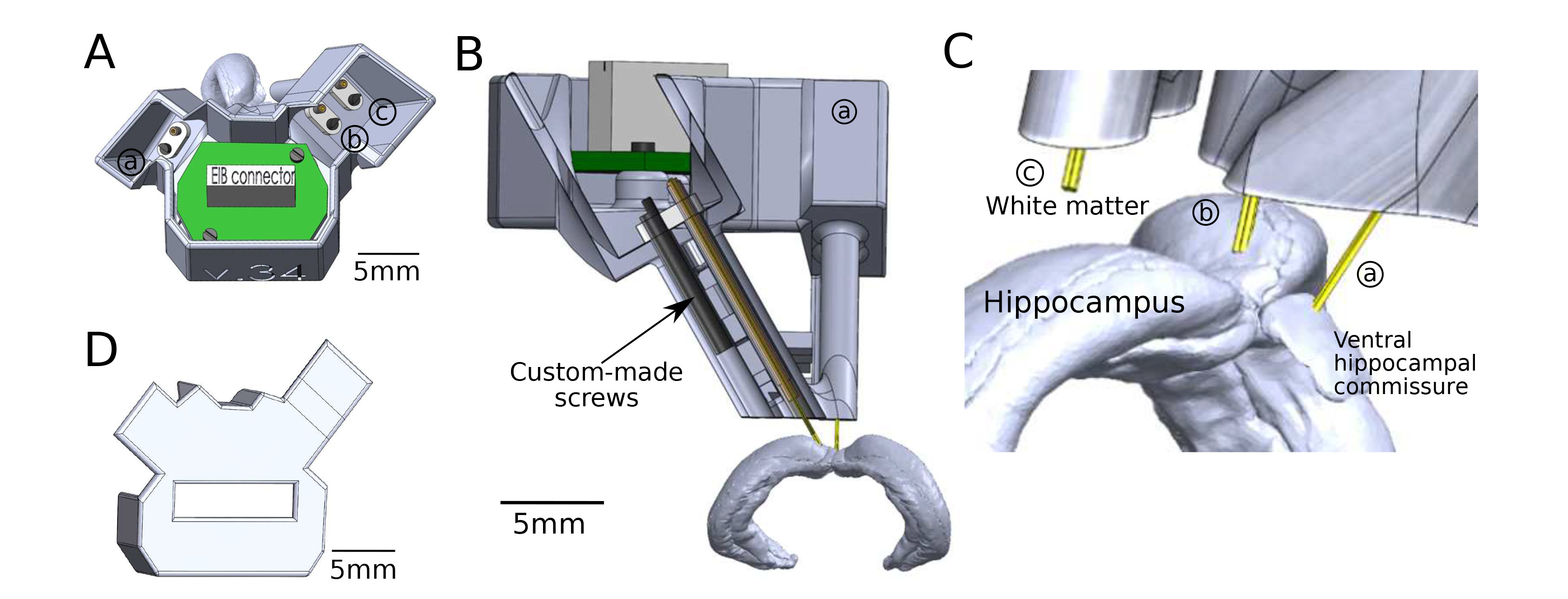
Fig. 1. Design and structure of the microdrive. (A) Top view of a 3D CAD model of the microdrive with electrical interface board (EIB). a: Screw-driven shuttle for stimulation electrode targeting VHC. b: Screw-driven shuttle for tetrode targeting hippocampus CA1. c: Tetrode in the white matter for reference purposes. (B) Cross-section of one of the microdrive cannulas. The insertion depth of the stimulation electrode and tetrodes (yellow) were controlled by custom screws (black, arrow). (C) Close-up view of tetrodes emanating from the microdrive array and their target areas. (D) Cover of the drive for the protection of electrical components.
© Exp Neurobiol